SPI (Serial Peripheral Interface)
In UART, both the transmitting and receiving devices used timers to measure time and synchronize communication. In contrast, SPI performs data transmission and reception by synchronizing both sides with a dedicated clock signal. A chip select signal can also be used, allowing communication between one master and multiple slave devices. The disadvantage compared to UART is that SPI requires more signal lines to establish communication.
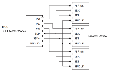
-
Transmission (Master -> Slave)
The master outputs the synchronization clock and simultaneously transmits data in alignment with this clock signal.

Figure 2.4 Example of SPI Transmission Format -
Reception (Slave -> Master)
The data transmitted from the slave side is received on the rising edge of the synchronous clock.

Figure 2.5 Example of SPI Reception Format
Note that the data transmission order (whether the most significant bit or the least significant bit is sent first), the clock polarity to be used, and the edges for data transmission/reception must be predetermined and configured in advance.
Next Column :I²C? Types and Characteristics of Serial Interfaces in Microcontrollers (MCUs)