I²C (Inter-Integrated Circuit)
Like SPI, I²C also supports one-to-multiple device connections. The major difference from SPI is that each slave has its own address, and the master can communicate only with the slave whose address matches by sending the desired slave's address. In addition, both the signal line and the clock line use the N-channel open-drain*1 method for output. This means the output can only drive a Low level, while during other periods, the lines are pulled up to High level by external pull-up resistors.
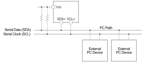
*1 N-Channel Open-Drain
For complementary outputs that provide both H-level and L-level signals, the method that outputs only the L-level is called N-channel open-drain, while the method that outputs only the H-level is called P-channel open-drain. In the case of the open-drain method, if it is N-channel, there is no output on the H side, so a pull-up resistor is added to bring the signal line to the H level and prevent a high-impedance state (a state that is neither H nor L).
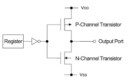
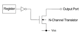
-
Transmission (Master -> Slave)
The master first sends the slave address and receives an acknowledgment signal from the slave. After that, the master transmits the data to the slave and receives an acknowledgment signal for each data.
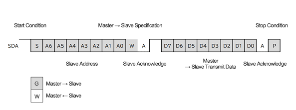
Figure 2.8 Transfer Format from Master to Slave in I²C -
Reception (Master <- Slave)
The master first sends the slave address and receives an acknowledgment signal from the slave. After that, the master receives the data output from the slave and sends an acknowledgment signal after each data is received.
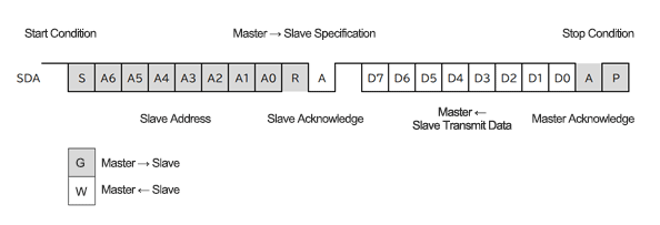
Figure 2.9 Transfer Format from Slave to Master in I²C
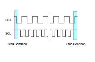
Additionally, the clock (SCL), start condition, and stop condition are as follows:
When SDA falls while SCL is High, it indicates a Start condition.
When SDA rises while SCL is High, it indicates a Stop condition.