What is an AD Converter (Analog-to-Digital Converter)?
What is an AD Converter?
An AD converter, also known as an "A/D converter," is a device that converts analog signals into digital signals. It is commonly referred to as an "Analog to Digital Converter," abbreviated as ADC.ADCs are essential components in electronic devices and microcontrollers. They enable digital systems to interpret real-world information, such as temperature, light, and sound, which naturally exists as continuous analog signals. Since digital devices cannot process analog signals directly, ADCs convert these signals into numerical values that software programs can handle. For example, the voltage output from a temperature sensor can be read by an ADC and then recorded or used for control as a digital value.
How an AD Converter Works: Circuits and Principles
The principle behind an AD converter (ADC) is to sample the voltage of an analog signal at fixed time intervals and convert it into a digital value. The analog-to-digital conversion process consists of three main steps: Sampling -> Quantization -> Encoding. This process involves components such as sample-and-hold circuits and encoders. The resolution of an ADC, expressed in bits, determines how finely it can distinguish between different analog signal levels. For example, a 12-bit ADC can represent values from 0 to 4095. One of the most common types of ADCs is the Successive Approximation Register (SAR) ADC. It includes a reference voltage, a comparator, and a digital control circuit, and it works by gradually narrowing down to the closest digital value. Another type is the Delta-Sigma ADC, which offers high-precision analog-to-digital conversion. It is highly resistant to noise and is well-suited for applications such as audio processing and sensor measurements.
How to Use an AD Converter: Main Applications and Practical Examples
Sensor Measurement
AD converters (ADCs) are used to digitize analog signals from sensors that measure temperature, humidity, light, pressure, and more, so that they can be processed by microcontrollers. This technology is essential in IoT devices and smart home appliances.
Audio Processing
Audio signals from microphones are analog, but by converting them into digital signals using an AD converter, they can be recorded, recognized, or transmitted. ADCs are widely used in smart speakers and communication devices.
Medical Devices
By converting biological signals such as electrocardiograms (ECG) and electroencephalograms (EEG) from analog to digital, it becomes possible to digitally process and record them. This field requires highly accurate ADCs. Devices such as ECG monitors, EEG machines, blood pressure monitors, and pulse oximeters rely on precise conversion of very small signals.
Industrial Control
In factory automation systems, information from sensors is digitized using AD converters and then processed by PLCs or microcontrollers for control purposes. Real-time performance and reliability are critical in these applications.
What is Epson's AD Conversion Technology "RF Conversion"?
Generally, "RF" stands for Radio Frequency, referring to the electromagnetic frequencies used in wireless communication. However, in this context, R stands for Resistance and F stands for Frequency. In other words, it refers to the process of converting resistance values into frequency.
Principle of RF Conversion
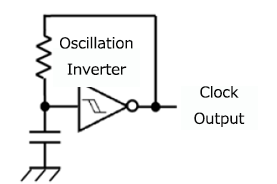
To convert a resistance value into a frequency, a CR oscillator circuit is constructed using the resistor to be measured. A CR oscillator is a circuit that combines a capacitor (C), a resistor (R), and an oscillator inverter to output a frequency (clock signal). When the resistance or the capacitance changes, the oscillation frequency also changes accordingly.
In contrast, Epson's RF converter adopts a unique method based on "time" and "oscillation count" rather than voltage levels.

Why RF Conversion Improves AD Conversion Accuracy
Conventional AD converters (such as successive approximation types) convert analog input voltages into digital values by comparing them with a reference voltage. To improve accuracy, the number of bits must be increased. However, as the bit count increases, the resolution becomes extremely fine, making the system more susceptible to noise and circuit limitations. As a result, practical resolution is typically limited to around 12 to 16 bits.
In contrast, Epson's RF converter adopts a unique method based on "time" and "oscillation count" rather than voltage levels.
-
Time Defined by Reference Oscillator
A highly stable reference oscillator circuit precisely defines a fixed measurement time.
-
Counting Oscillations from Sensor Resistance
The number of oscillations generated by an oscillator circuit that includes the sensor resistance (e.g., a temperature sensor) is counted within that fixed time period.
-
Improved Accuracy Through Ratio Measurement
By taking the ratio between the fixed time (from the reference oscillator) and the number of oscillations (from the sensor oscillator), changes in the sensor's resistance can be digitized with high precision.
This mechanism allows the system to avoid the direct limitations of bit count and resolution found in conventional ADCs. For example, using a 700 kHz reference clock and measuring over 2.39 seconds can theoretically achieve a resolution equivalent to 24 bits (16,777,216 counts). The only drawback is that higher accuracy requires longer measurement times. However, this can also be seen as an advantage: the more time you invest, the greater the precision you can achieve.
"The reason EPSON's RF converter is highly accurate lies in its method of measurement: it uses time generated by a reference oscillator as a standard ruler to measure the sensor's oscillation count as a ratio."
