What is a Microcontroller's Watchdog Timer (WDT) in Microcontrollers?
What is a Watchdog Timer?
A watchdog timer (WDT) is like a guard dog that watches for suspicious activity at the entrance. Similarly, a watchdog timer monitors the system, and if it determines that the system is malfunctioning, it triggers a system reset or an interrupt. In this article, we will explain the watchdog timer used in systems centered around microcontrollers (MCUs).

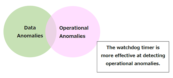
When classifying MCU malfunctions from a phenomenological perspective, they can be broadly divided into two categories: data anomalies and operational anomalies.
- Data Anomalies
- Abnormal values occur in registers or RAM data in the MCU.
- The results of arithmetic operations become abnormal values.
- Operational Anomalies
- The program counter in the CPU changes and jumps to an unexpected address.
- Abnormal values occur in registers or RAM in the MCU, and the program counter referencing these values also becomes abnormal.
- The results of arithmetic operations become abnormal, and the program counter referencing these results also becomes abnormal.
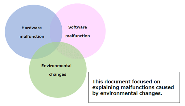
Furthermore, when classifying MCU malfunctions from a causal perspective, they can be divided into three categories: hardware issues, software issues, and environmental changes.
- Hardware Issues
- Issues in the MCU circuitry
- Issues in MCU manufacturing
- Characteristic variations due to aging or other changes in the MCU
- Software Issues
- Issues in software specifications
- Issues in software evaluation
- Issues Caused by Operating Environment
- Unstable operating power supply
- Noise interference
Mechanism of the Watchdog Timer
Method for Detecting Malfunctions in the Watchdog Timer
In fact, determining whether the MCU is malfunctioning or not is a very difficult problem. Even if a human can intuitively distinguish between normal and abnormal operation while using the product, it is extremely difficult for the MCU itself to make that judgment.
In a watchdog timer, the MCU's software is tasked with performing a simple operation within a time limit. If the operation fails to meet the time constraint, it is judged as a malfunction, and a system reset or interrupt is triggered. Of course, the intended main processing continues to run in parallel.
With this method, it is difficult to monitor all registers and RAM data. While it can detect "operational anomalies," it tends to be less effective at detecting "data anomalies."
Furthermore, among the causes of malfunctions, if the root cause lies in the hardware or software itself, then the reliability of the "simple time-limited task" executed by the MCU becomes questionable. Therefore, such factors should be eliminated in advance.*1
Significance of the Watchdog Timer
The malfunction detection function of the watchdog timer is not perfect. However, it holds significance in that it can help the system recover to a correct state within its capabilities, even under unusual environmental changes that typically should not occur-such as unstable power supply or noise interference. For example, in a product using an MCU, if the system freezes due to external noise, the use of a watchdog timer increases the likelihood that the system will reboot itself. However, if the reboot is triggered by a system reset, continuous operation cannot be expected. In the case of a clock, for instance, it may reset to 00:00. On the other hand, if the reboot is triggered by an interrupt, the system may not be reinitialized, but there is a high possibility that registers or RAM data have been corrupted. If such recovery methods are problematic, it is necessary to implement measures to prevent the MCU from malfunctioning in the first place.
*1: Even when unintended behavior occurs due to hardware or software defects, it may still be detected by the watchdog timer. However, in this document, we proceed under the assumption that the hardware and software are functioning correctly.
Watchdog Timer Circuit
Circuit Configuration
For example, a circuit can be configured by inputting a 32.768 kHz clock signal, which is commonly used as a reference oscillator in devices like clocks, and then dividing it by 128 and further by 1,024. Dividing by 128 yields a 256 Hz clock, and further dividing by 1,024 results in a 1/4 Hz clock, allowing an overflow output every 4 seconds. This overflow output is used as a system reset or interrupt signal for the MCU.

In a watchdog timer that generates a system reset signal, the 32.768 kHz signal is continuously input. Therefore, if left unattended, a system reset signal will be triggered after approximately 4 seconds*2, causing the MCU to initialize itself. If this occurs, the MCU will no longer be able to fulfill its intended function. To prevent this, the 10-bit counter inside the watchdog timer must be cleared within 4 seconds to avoid triggering a system reset.
Constraints
Since the counter overflow occurs at fixed intervals, clearing the counter within that time frame is the fundamental operation of the watchdog timer. But what happens if the MCU malfunctions and the following situations occur?
- The software malfunctions and stops the counter clock.
- The software malfunctions and continuously clears the counter.
In these cases, the counter overflow will not occur, so the watchdog timer will not trigger a system reset or interrupt. However, many MCU manufacturers have implemented countermeasures, such as requiring specific procedures to stop the clock or allowing the counter to be cleared only under certain conditions.
*2: In this document, to facilitate understanding, the initialization operation of the MCU is referred to as a "system reset," and the initialization of the watchdog timer counter is referred to as "clear."
Types of Internal and External Watchdog Timers
What is an Internal Watchdog Timer?
In recent years, most MCUs come equipped with a built-in watchdog timer. Therefore, in systems using MCUs, it is common to use the internal watchdog timer.
What is an External Watchdog Timer?
For MCUs that do not have a built-in watchdog timer, or when higher reliability is required, an external watchdog timer may be used. While the principle is the same as that of an internal watchdog timer, it operates independently from the MCU, which generally provides higher reliability. However, it also leads to increased cost.
Comparison of Advantages and Disadvantages of Internal and External Watchdog Timers
The following table summarizes a comparison between internal and external watchdog timers:
| WDT Type | Advantages | Disadvantages |
|---|---|---|
| Internal | No additional cost. Save PCB space. |
Functions reliably even if the MCU malfunctions. |
| External | May not function properly if the MCU itself malfunctions. | Increases cost. |
Main Functions of the Watchdog Timer
A microcontroller is a type of semiconductor product (IC), but it is one that can integrate a variety of components.
The basic components of a watchdog timer are as follows:

① Frequency Divider Circuit
This circuit divides the Clock Source to output a fixed clock signal. In this example, 32.768 kHz input is divided to produce 256 Hz output.
② Counting Circuit
This circuit counts the input clock and measures a specified time interval. Here, it receives 256 Hz input and measures 4 seconds.
③ WDT Clear Circuit
This circuit clears the counter to prevent the generation of system reset or interrupt signals.
④ System Reset / Interrupt Generation Circuit
This circuit generates a system reset or interrupt signal to the MCU. When the counter is overflow,, a system reset or interrupt is triggered.
Precautions for Using the Watchdog Timer
The basic precautions for using a watchdog timer can be summarized as follows:
- The Watchdog Timer Is Not Perfect
Since malfunction detection is based on whether the MCU successfully performs a "simple time-limited task," there are cases where malfunctions may go undetected. Of course, using an external watchdog timer or designing a more complex internal watchdog timer circuit can improve reliability, but these approaches also increase costs and add complexity to software development. - Be Careful About When to Clear the Watchdog Timer Counter
In typical software flow, the counter must be cleared within a certain time frame. Clearing the counter in sync with a timer interrupt can simplify software processing. However, since timer interrupts are hardware-driven, synchronizing counter clearing with them may result in stable interrupt generation-even during malfunctions-leading to the counter being cleared unintentionally. Therefore, it is recommended to clear the counter at unpredictable timings during normal software execution. - The Watchdog Timer Clock Must Not Be Stopped
Even temporarily, the watchdog timer clock must not be stopped. For example, even if software that stops the clock is placed in a program area that is not normally executed, there is a risk that the routine may be executed during a malfunction.
Watchdog Timer Built into Epson Microcontrollers
Main Features of the Watchdog Timer Built into Epson Microcontrollers
There are mainly two types of watchdog timers: "WDT" and "WDT2."
1)WDT
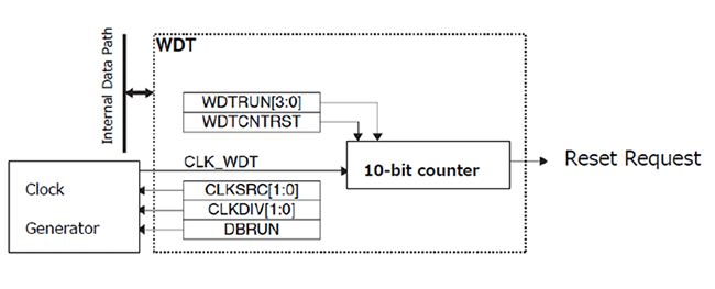
The WDT is a timer that performs only system resets. It includes functions for starting and stopping a 10-bit counter, as well as clearing the counter.
2)WDT2
Compared to the WDT, WDT2 includes additional functionality such as system reset and NMI (Non-Maskable Interrupt) generation using comparator-based compare match.
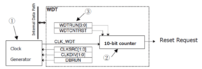
① The clock generator generates the operating clock (CLK_WDT) for watchdog timer which is adjusted to approximately 256Hz.
② The 10-bit counter counts this clock input, and an overflow occurs every 4 seconds.
③ WDTRUN controls the start/stop operation of the counter, and WDTCNTRST is the register used to clear the counter. These registers can be written to by software. If the 10-bit counter is not cleared within the specified time, a system reset will occur (in WDT2, an NMI*3 can also be selected).
For detailed operation, please refer to the technical manual provided for each specific model.
*3 NMI (Non-Maskable Interrupt): An interrupt that cannot be masked. It is typically used for high-priority or emergency interrupts.
Overview and Lineup of Epson Microcontrollers
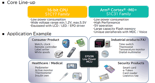
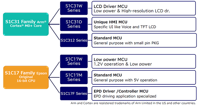
Epson offers two core microcontroller families: the S1C17 Family, which features 16-bit MCUs, and the S1C31 Family, which features 32-bit MCUs based on the Cortex-M0+ core. All currently released models are equipped with a built-in watchdog timer.
How to Use the Watchdog Timer Built into Epson Microcontrollers
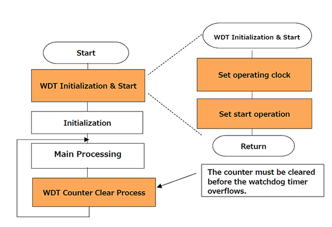
The procedure for using the watchdog timer (WDT2) in Epson MCUs is explained using a flowchart.
The "WDT Initialization & Start" process is executed only once at the beginning. The "Counter Clear Process" should be inserted during the normal operation of the software and must be executed before the watchdog timer counter overflows.
Operating Clock Configuration
- Disable System Protection *4
- If the clock source is stopped, enable the clock using the clock generator
- Select the clock source
- Set the clock frequency
- Enable System Protection
Startup Configuration:
- Disable system protection
- Set the WDT2 operating clock
- Select the WDT2 operating mode (NMI/Reset)
- Set the WDT2 trigger interval
- Clear the WDT2 counter
- Start the WDT2
- Enable system protection
Counter Clear Procedure
- Disable system protection
- Clear the WDT2 counter
- Enable system protection
*4 System Protection: In Epson MCUs (S1C17/31 Family), a protection mechanism is implemented to prevent easy modification of particularly important registers. Locking and unlocking are possible by writing a specific code to designated registers.
